Most design engineers understand that great products start with great design—but not all designs are equally manufacturable. When a part arrives at a toolmaker without proper Design for Manufacturability (DFM) review, expensive problems emerge: costly tooling revisions, longer lead times, and high scrap rates during production ramp-up. Many of these issues could have been prevented during the design phase when changes are still inexpensive.
Let's walk through the ten design mistakes that most commonly inflate injection molding costs, and what you should review before releasing CAD to tooling.
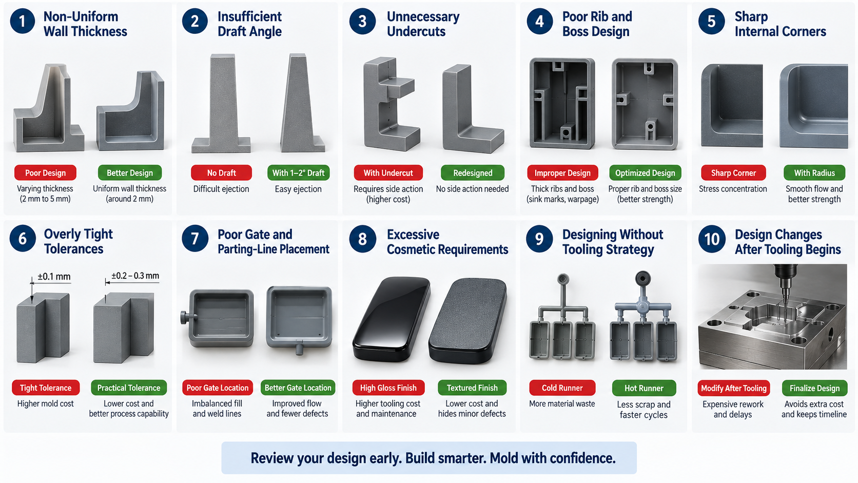
1. Non-Uniform Wall Thickness
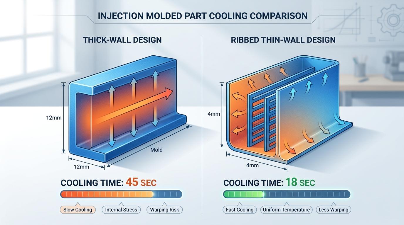
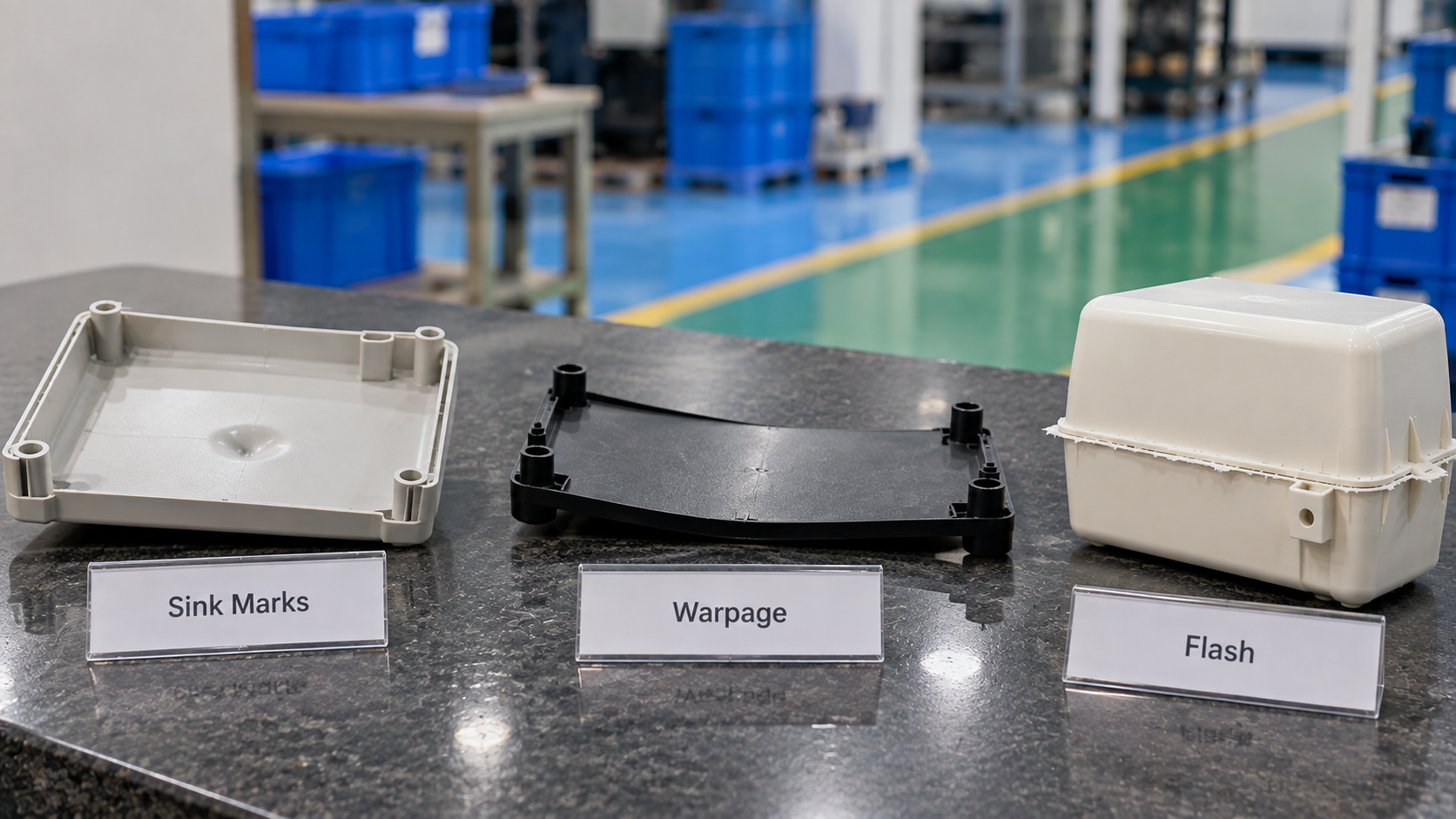
This is the most frequent design problem. When walls vary significantly in thickness—say, a nominal 2 mm wall next to a 5 mm thick boss—the material cools at different rates. Thick sections cool slowly, causing sink marks on cosmetic surfaces. Thin sections fill first and may freeze before thicker areas are pressurized, trapping voids or creating short shots.
The fix is straightforward: maintain wall thickness as constant as possible (ideally 1.2–3.0 mm depending on material). When strength requires thicker sections, use ribs instead of solid bulk. Smooth thickness transitions with generous fillets and tapers rather than abrupt steps.
2. Insufficient Draft Angle
Parts designed with zero or minimal draft angle (vertical walls) stick hard to the mold during cooling. The material shrinks onto the core, increasing ejection friction. Molders compensate by increasing ejection force, causing part damage, slower cycles, and increased wear on tooling.
A practical starting point: 1–2 degrees of draft on all surfaces parallel to the mold opening direction. Textured surfaces need more (3–5 degrees depending on texture depth). This small change eliminates costly ejection problems and extends tool life.
3. Unnecessary Undercuts
Undercuts (features that prevent straight-line part ejection) force toolmakers to add slides, lifters, or core pullers. Each adds cost, complexity, maintenance burden, and risk of malfunction.
Before designing an undercut, ask: Is this feature functionally necessary, or does it solve an assembly or aesthetic problem that could be solved differently? Often, a small design change—relocating a feature, adjusting parting-line position, or using assembly instead of molded-in functionality—eliminates the need for expensive side actions.
4. Poor Rib and Boss Design
Ribs should reinforce parts without adding mass. But ribs that are too thick (>60% of wall thickness), too tall (>3× their thickness), or spaced too close to walls or each other create thick sections that sink, warp, or void internally. Bosses designed without draft, taper, or proper thickness sink visibly and often split under load.
Practical guidelines: Rib thickness 40–60% of nominal wall, with 1–1.5° draft. Boss wall thickness 60% of nominal, tapered down toward its base. Space ribs at least 2× the wall thickness apart to allow proper mold-wall cooling.
5. Sharp Internal Corners
Sharp corners concentrate stress and create flow disturbances during filling. Melt can't flow smoothly around 90° angles, causing weld lines, burn marks, or short shots in tight corners.
Add generous fillets (at least 0.5–1 mm radius) at all internal transitions. This improves flow, reduces stress concentration, and improves cosmetics.
6. Overly Tight Tolerances
Specifying tolerances tighter than necessary inflates mold precision requirements and may demand additional post-molding operations (trimming, machining, sorting). A tolerance of ±0.1 mm across all dimensions is often impossible to hold consistently without tight process control and frequent tool adjustments.
Understand what your assembly or function actually requires. Typical molded tolerances are ±0.2–0.3 mm for most applications. Only critical features need tighter control.
7. Poor Gate and Parting-Line Placement
Gate location determines how the mold fills and where weld lines form. A poorly positioned gate (e.g., remote from thick sections, or placed where flow fronts collide) requires higher injection pressure and leads to defects.
Parting-line placement affects draft requirements, core/cavity balance, and cosmetics. Placing a parting line across a cosmetic surface creates a visible witness line that's expensive to hide.
8. Excessive Cosmetic Requirements
Specifying Class A finish, tight dimensional tolerances, and mirror gloss across large surfaces drives up tooling precision and often requires post-mold polishing or deflashing. Not all surfaces need this level of finish.
Identify truly cosmetic areas and specify appropriately. Use texture to hide minor imperfections and reduce mold-surface maintenance costs.
9. Designing Without Considering Tooling Strategy
Some designs make assumptions about tooling approach that aren't optimal. For example, a design might assume a cold-runner system when a hot-runner tool would reduce scrap and cycle time. Or it might not account for multi-cavity balancing, requiring the molder to compromise on cavity count or accept part-to-part variation.
Early conversations with your toolmaker about cavity count, runner type, and cooling strategy can prevent design changes that derail timelines.
10. Design Changes After Tooling Begins
Changing dimensions, adding features, or modifying geometry after steel is cut is exponentially expensive. EDM work, re-hardening, and qualification trials cost thousands and delay production.
Lock your design before releasing to tooling. Budget time for a thorough DFM review and mold-flow simulation while changes are still free.
BEFORE YOU RELEASE THE CAD: Design Review Checklist
Before sending your part to a toolmaker, review these items:
- Wall thickness is uniform (1.2–3.0 mm range for your material)?
- All surfaces parallel to mold opening have 1–2° minimum draft?
- Ribs are 40–60% of wall thickness, properly spaced?
- Bosses taper toward their base, with 60% wall thickness?
- All internal corners have ≥0.5 mm radius?
- Undercuts are functionally necessary (and discussed with toolmaker)?
- Tolerances are only as tight as assembly/function requires?
- Gate location is positioned for good fill balance?
- Parting line avoids cosmetic surfaces?
- Cosmetic specifications are realistic (texture/matte vs. Class A)?
FD GROUP PERSPECTIVE
Design-first approach saves money—but only if problems are caught early. FD Group's DFM review identifies geometry, ejection, gating, and cost risks before mold steel is cut. Our engineering team works with your CAD, runs mold-flow simulation, and flags issues while changes are still inexpensive.
The goal isn't to sell you a bigger mold. It's to help you reach production faster, with fewer surprises, and lower total cost.
Next step: Share your CAD drawing and material specification. FD Group's engineering team will provide detailed DFM feedback within 48 hours.
FREQUENTLY ASKED QUESTIONS
A: Usually 3–5 business days. This upfront investment typically saves 2–4 weeks in tooling delays caused by design issues.
A: STEP format (preferred) or IGES. Include 2D drawings with tolerances, material specification, and required surface finishes.
A: Minor adjustments (gate size, cooling channel depth) are manageable. Geometric changes are expensive and should be avoided after steel is cut.
A: Yes. Simulation identifies filling imbalance, air entrapment, sink-mark risk, and warpage predictions before tooling.
A: We can discuss manufacturability constraints during concept development, which often improves the final design.
A: We operate under full NDA. All designs remain your property.
A: 1.2–3.0 mm for most materials (ABS, PP, PA6). Some high-performance resins can go thinner or thicker depending on part geometry.
A: Yes. More cavities increase tooling cost but lower per-part mold cost. Your toolmaker should model different cavity counts in the quotation.