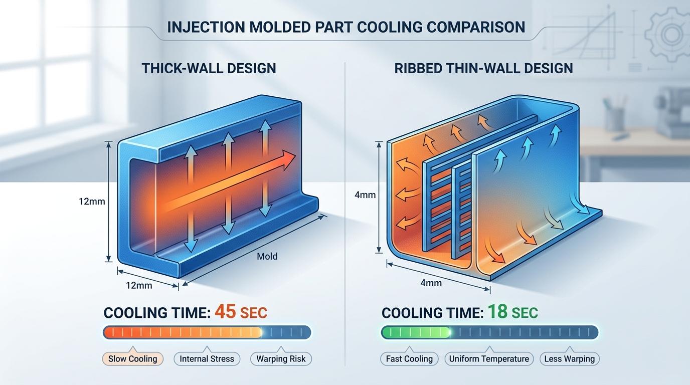
One of the most common design mistakes is using thick walls for structural strength. Thick sections cool slowly, shrink non-uniformly, and create sink marks on cosmetic surfaces. The better approach is using ribs and bosses—structural reinforcement that adds strength without mass.
But rib and boss design isn't intuitive. Get the proportions wrong, and you trade one problem for another: voids, warpage, cosmetic defects, or weak stress concentration points.
Why Use Ribs Instead of Thick Walls?
A solid 4 mm thick wall in a 2 mm nominal part creates a 2:1 thickness ratio. This means the thick section cools in 4–5 minutes while thin sections freeze in under a minute, creating differential shrinkage, internal stress, and visible sink marks.
A rib approach—adding a 1 mm rib to a 2 mm wall—provides similar strength but more uniform cooling. Material doesn't pool, cooling is faster and more balanced, and cosmetic surfaces remain flat.
Structural principle: Distribute material where it's needed for strength. Concentrate it in ribs parallel to stress axes, not as uniform bulk.
Rib Thickness: Finding the Balance
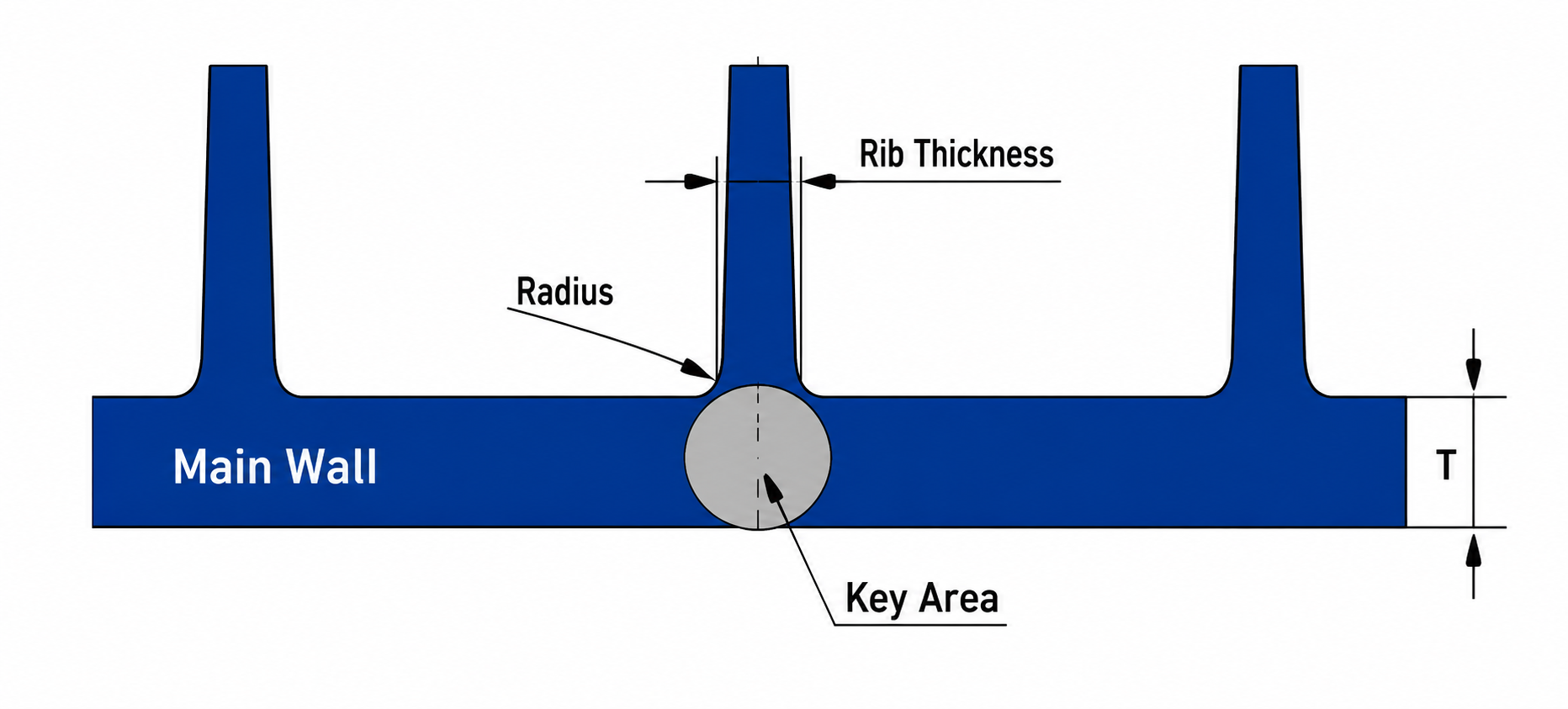
Rib thickness is the single most important rib dimension. Too thin and it doesn't add strength. Too thick and it becomes another mass-cooling problem.
Practical guideline: Rib thickness 40–60% of nominal wall thickness.
If your nominal wall is 2.0 mm, aim for a 0.8–1.2 mm rib. For a 3 mm wall, 1.2–1.8 mm ribs.
Why not 100% wall thickness? Because a rib as thick as the wall is essentially adding another solid section—no benefit to cooling balance.
Material affects this: Filled materials (glass-filled nylon, carbon-filled resins) behave differently than unfilled resins. Consult material datasheets for recommended rib thickness relative to wall.
Rib Height: Structural Efficiency vs. Cooling Risk
A rib's height-to-thickness ratio determines how much bending stiffness it contributes. Tall, thin ribs are structurally efficient. But very tall ribs (>4× their thickness) can bridge across cooling channels, trap heat, and create thick local sections at their base where they join the wall.
Practical guideline: Rib height 2–3× rib thickness, maximum.
If ribs are 1 mm thick, keep height to 2–3 mm. Taller ribs exist but require special cooling strategy and increase sink-mark risk at the rib base.
Rib Spacing: Avoiding Thin Mold Walls
When ribs are spaced too close together, the mold material between them (the "land") becomes very thin. Thin mold lands are difficult to manufacture accurately, expensive to cool, and prone to breakage during production.
Practical guideline: Space parallel ribs at least 2× the nominal wall thickness apart.
If wall thickness is 2 mm, space ribs at least 4 mm apart (center to center or edge to edge—clarify with your toolmaker). This leaves adequate mold material between ribs for machining and cooling.
Rib Draft and Base Radius
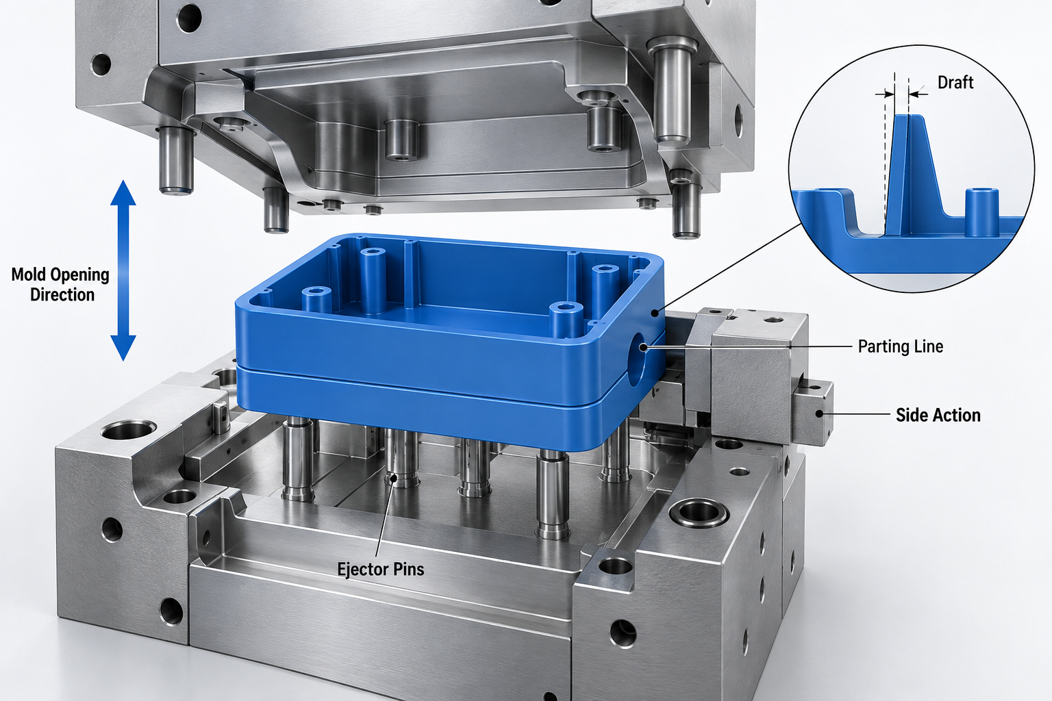
Ribs must be drafted for ejection. Use 1–1.5° draft on both sides of each rib, measured from the rib centerline.
At the rib base (where the rib joins the wall), use a generous fillet—at least 0.5–1.0 mm radius. Sharp rib bases concentrate stress and create flow disturbances during filling, causing weld lines or weak zones.
A tapered rib (thicker at base, thinner at height) distributes stress more smoothly and reduces sink-mark risk at the base.
Boss Design: Common Mistakes
Bosses are solid cylindrical posts used for screw holes, assembly inserts, or fastening points. Most boss failures trace to three mistakes:
- Bosses that are too thick: A boss as thick as the wall creates another localized thick section prone to sink and void. Keep boss wall thickness around 60% of nominal wall.
- Bosses without draft: A vertical-sided boss will stick in the mold. Add 1–2° draft.
- Bosses without taper: A boss with parallel walls and a sharp base creates high stress and poor cooling. Taper the boss—thicker at the base, tapering to a thinner top—to distribute stress and improve cooling.
Practical boss design:
- Outer diameter: Sized for the assembly function (e.g., fit around a screw)
- Wall thickness: 60% of nominal wall
- Height: Maximum 3× boss outer diameter (or discuss with toolmaker)
- Taper: 1–2° per side
- Base radius: ≥1.0 mm fillet
For screw bosses, the hole is typically cored (molded in). The cored hole should be slightly undersize (e.g., #4-40 tap hole cored as 0.089" instead of final 0.0935") to allow tapping and allow for shrinkage variation.
Gussets: Triangular Reinforcement
Gussets are triangular reinforcement ribs connecting orthogonal walls (e.g., where a wall meets a base). They distribute load more smoothly than abrupt corners.
Gusset thickness 50–60% of nominal wall works well. Keep gusset height to 2–3× their thickness.
Stress Concentration and Assembly Loads
Ribs and bosses create stress concentrations—points where stress flows narrow and intensify. Position ribs to align with load paths. Avoid sharp transitions between different-thickness sections.
A rib-to-wall transition with a sharp corner concentrates stress. A tapered or filleted transition spreads the stress more safely.
Warpage and Orientation Effects
Ribs aligned parallel to each other create directional cooling and material orientation. This can cause anisotropic shrinkage—the part shrinks more in one direction than another, causing warpage.
Consider rib orientation relative to part shrinkage direction. Cross-rib patterns (ribs oriented in different directions) create more uniform cooling, but they're more complex to mold.
RIB AND BOSS DFM CHECKLIST
- Rib thickness is 40–60% of nominal wall?
- Rib height is 2–3× rib thickness?
- Parallel ribs are spaced ≥2× wall thickness apart?
- Ribs have 1–1.5° draft on both sides?
- Rib base has ≥0.5 mm fillet?
- Boss wall thickness is 60% of nominal wall?
- Bosses have 1–2° draft?
- Boss base is tapered or filleted?
- Screw-boss hole is slightly undersize for tapping?
- Gusset thickness is 50–60% of wall?
- No sharp corners between ribs and walls?
FD GROUP PERSPECTIVE
Rib and boss proportions seem like small details, but they're the difference between a part that holds tight dimensional control and one that warps or fractures in the field. Our DFM review specifically evaluates rib geometry, runs cooling simulation, and flags ribs that will cause sink marks or warpage.
Talk to us about your part's structural requirements early. We'll help you place ribs strategically, size them for manufacturability, and ensure cooling is balanced. Request a DFM review.
FREQUENTLY ASKED QUESTIONS
A: Not really. Thicker ribs create cooling problems that hurt strength through warpage and internal voids. Better to add more ribs or use a higher-strength material.
A: Cross-rib patterns add complexity but create more uniform cooling. Discuss this early with your toolmaker.
A: Specify nominal thickness, height, draft angle, and base radius. Show spacing between parallel ribs. CAD 3D models are clearer than 2D drawings.
A: Yes, but they must be offset (not directly opposite) to avoid thin mold lands. Offset them by half the rib spacing.
A: Filled resins (glass-filled nylon) have different shrinkage and flowability. Rib proportions may need adjustment. Confirm with your resin supplier and molder.
A: Usually negligible. Taper can be EDM'd into the core without major extra cost. It's worth doing.
A: Sometimes. If a parting line runs down the center of a rib, the rib can hide the witness line. Discuss with your mold designer.
A: Practical maximum is 4–5× rib thickness for most materials, but anything >3× height requires thermal analysis. Taller ribs risk sink marks at the base.