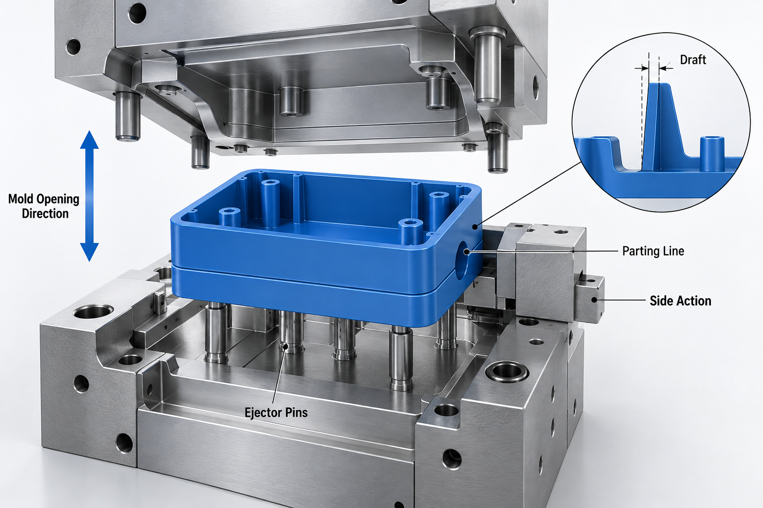
Demolding—the moment the mold opens and the part separates—seems simple. But poor demolding design creates friction, part damage, long cycle times, and expensive ejection-system complexity. The best demolding parts are designed from the beginning with mold opening direction in mind.
Let's explore the practical design decisions that make demolding reliable, repeatable, and fast.
Understand the Mold Opening Direction
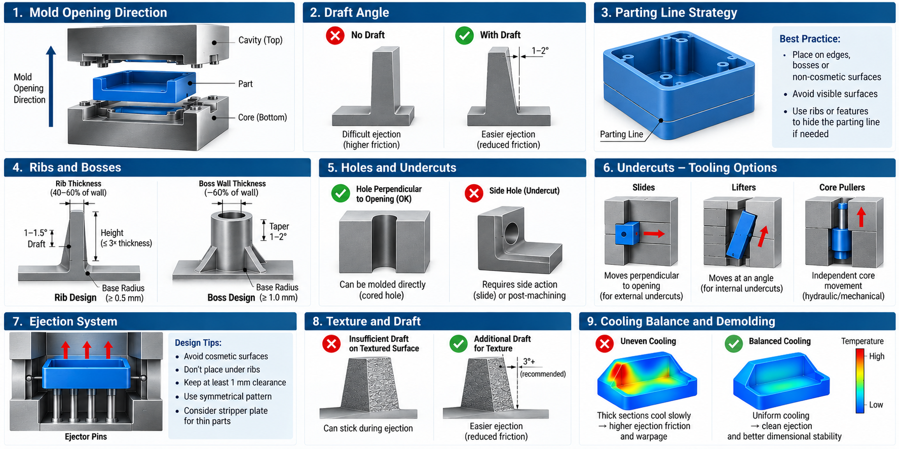
Every part has a primary mold opening direction—the direction the cavity and core separate. In most 2-plate molds, this is vertical. All design decisions that follow must account for this single direction.
Surfaces parallel to the opening direction need draft. Features perpendicular to the opening direction (holes, slots) require side actions. Features that prevent straight-line separation are undercuts and demand special handling.
Design rule: Identify your opening direction early. Every feature should either be parallel to it (and drafted), perpendicular to it (and gated cleanly), or justified as a necessary undercut with planned tooling to handle it.
Draft Angle: The Foundational Ejection Tool
Draft is a taper applied to surfaces parallel to mold opening. It reduces friction as the part shrinks and cools onto the core. Without adequate draft, ejection becomes a battle against friction.
Practical starting points:
- Outer (cavity) surfaces: 1–1.5° draft
- Inner (core) surfaces: 1.5–2° draft (higher because the part shrinks onto the core)
- Textured surfaces: Add 1° for every 25 micrometers of texture depth
- Deep cavities (>50 mm): Consider 2–3° draft
Draft isn't free—it affects part dimensions and visual appearance—but skimping on it inflates ejection costs downstream.
Parting Line Strategy
The parting line is where the mold halves separate. Positioning it poorly creates visible witness lines on cosmetic surfaces or traps material in tight areas that resist demolding.
Best practice: Place parting lines on edges, bosses, or non-cosmetic surfaces. If a parting line must cross a visible surface, use a gentle boss or rib to hide it.
Running mold-flow analysis helps visualize where plastic flows relative to the parting line, revealing potential hang-up zones.
Ribs and Bosses: Ejection Challenges
Ribs and bosses create internal cavity complexity. When ribs are tall and closely spaced, they form thin mold-wall sections that are difficult to cool and easy to damage during ejection.
Design for demolding:
- Space ribs at least 2× wall thickness apart
- Keep rib height to 3× rib thickness
- Draft ribs at 1–1.5°
- Taper bosses toward their base
- Avoid ribs that trap cooling water or ejector pins
Holes and Undercuts: Manage Complexity
Small holes can be cored (molded in) if positioned carefully relative to the opening direction. Holes perpendicular to opening are simple. Holes parallel to opening require either angled cores or, more commonly, drilling after molding.
Side holes and slots are undercuts. They require slides (side actions) that move perpendicular to mold opening. Each slide adds cost, maintenance, and risk of jamming. If a side hole is necessary, place it where the slide motion doesn't interfere with ejection or other features.
Question: Can the feature be added after molding (drilling, tapping, assembly) instead of molding in? Often, yes—and it's cheaper.
Undercuts: Cost vs. Necessity
An undercut is any feature that prevents straight-line part ejection. External hooks, internal recesses, snap-fit features—all are undercuts.
Undercuts require special tooling:
- Slides: Move perpendicular to mold opening. Used for external undercuts like side holes.
- Lifters: Move at an angle. Better for internal undercuts like snap-fit pockets.
- Core pullers: Hydraulic or mechanical cores that move independently.
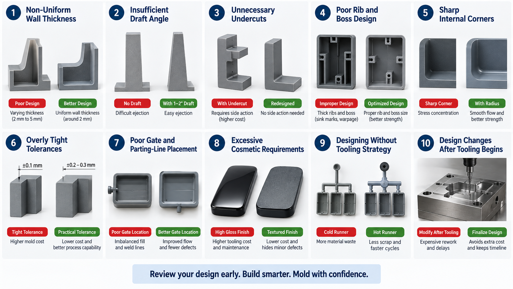
Each mechanism adds 15–40% to mold cost and introduces maintenance risk. Before designing an undercut, ask: Is this feature functionally critical, or can it be redesigned away?
Ejection System Design
Parts must separate from both cavity and core. Most single-cavity parts stay on the core and are ejected by pins (or a stripper plate for thin parts). Multi-cavity molds may use ejector sleeves or rack-and-pinion systems.
Design tips:
- Avoid designing features directly under ejector pin locations (they leave marks)
- Ensure ejector pins don't penetrate structural ribs
- Leave at least 1 mm clearance between pins and cosmetic surfaces
- Position pins in symmetrical patterns to avoid imbalanced ejection
Gate Position and Its Effect on Demolding
Gate location affects how the part fills—and indirectly affects demolding. A gate positioned too close to an undercut can create a thick section near the undercut, making demolding harder. A gate positioned far from a thick section may not pressurize it adequately, causing sink marks over critical features.
Good gate placement balances fill flow with part geometry, ensuring uniform cooling and no trapped air that could cause sticking.
Cooling Balance and Demolding
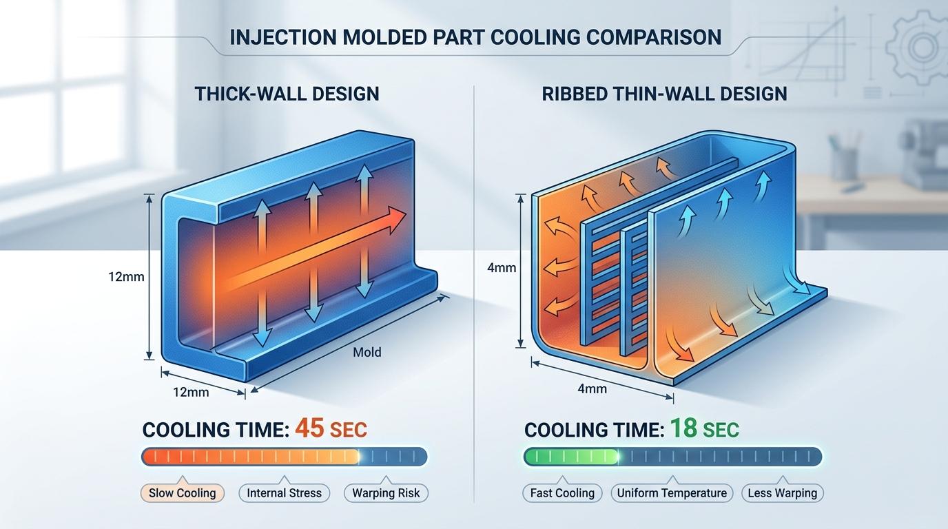
Uneven cooling creates stress, warpage, and parts that stick in the mold from differential shrinkage. Balanced cooling ensures the part releases cleanly.
Cooling strategy affects demolding: If thick sections cool slowly while thin sections freeze quickly, the thin areas shrink first, creating internal stresses that can actually increase demolding friction.
Work with your mold designer on cooling-channel placement. Proper channels cool the part uniformly, reducing ejection resistance.
Texture and Draft Interaction
Textured surfaces require more draft because the texture creates mechanical engagement between the part and mold surface. A textured surface with insufficient draft will stick.
If you need texture for cosmetic or grip purposes, budget for additional draft. Alternatively, use texture only on non-draft surfaces (perpendicular to opening direction) and keep draft surfaces matte or polished.
DEMOLDING DESIGN CHECKLIST
- Primary mold opening direction is clearly defined?
- All surfaces parallel to opening have adequate draft (1–2° minimum)?
- Parting line avoids cosmetic surfaces?
- Ribs are spaced ≥2× wall thickness apart?
- Bosses taper toward base and are drafted?
- Undercuts are functionally justified and tooling approach is known?
- Ejector pin locations are specified and avoid cosmetic surfaces?
- Textured surfaces have extra draft (+1° per texture depth)?
- No sharp interior corners that could cause sticking?
- Cooling-channel strategy is discussed with toolmaker?
FD GROUP PERSPECTIVE
Demolding problems rarely surprise anyone at production—they're visible during mold trials. But by then, fixes are expensive and time-consuming. Our DFM review specifically evaluates demolding geometry, simulates mold flow to identify sticking zones, and flags features that will cause production headaches.
Early design review means confident demolding, faster cycles, and lower defect rates. Talk to FD Group's engineering team about your part design.
FREQUENTLY ASKED QUESTIONS
A: 0.5° is the absolute minimum for most materials, but 1–2° is preferred for reliable production. Textured surfaces need 3°+.
A: Slides eliminate the need for draft on side-action surfaces, but they add cost and complexity. Draft on primary surfaces is still simpler.
A: The part either tears (scrap) or the ejection system forces it out, damaging cosmetics or structure. Either way, production stops and rework is needed.
A: Yes, if the part geometry allows. Stripper rings work well for thin-walled parts without deep internal features.
A: Communicate with your toolmaker during design review. Mold-flow simulation often reveals the optimal parting line before tooling.
A: Slides move perpendicular to mold opening (good for side holes). Lifters move at an angle (better for internal undercuts). Cost and complexity are similar.
A: Possibly, but it's slow, inconsistent, and labor-intensive. Automation requires proper draft and design.
A: Yes. Semi-crystalline resins (PP, nylon, POM) shrink more and grip tighter than amorphous resins (ABS, PC). More draft is needed for semi-crystalline materials.