Quality cannot be inspected into a part after the fact, but verification still matters, because a print means nothing until someone proves the molded part matches it. When buyers ask how we inspect injection molded parts, what they really want to know is whether our checks are rigorous enough to catch problems before parts reach their line. The honest answer is that good quality control is layered: it starts before the first shot and continues through final inspection and shipment. This article walks through that flow, the tools involved, and how we make sure the measurement data itself can be trusted.
It Starts Before the First Shot
Inspection begins with the material. Incoming resin is checked against its certificate of analysis, and moisture-sensitive polymers are dried to the supplier's recommendation, because a wet resin can degrade and shift both mechanical properties and dimensions. Verifying the right grade, color, and additive package up front prevents defects that no amount of downstream inspection can undo. Lot information is recorded so any question later can be traced back to a specific material batch.
First Article Inspection
Before a new job runs in earnest, a first article inspection (FAI) documents that the tool, the process, and the paperwork can produce a conforming part. Every dimension on the drawing is measured against a representative part and recorded. FAI is the baseline that later production is checked against. Because it is a topic in its own right, we cover it in detail in our [Internal Link: First Article Inspection] guide.
In-Process Checks at the Press
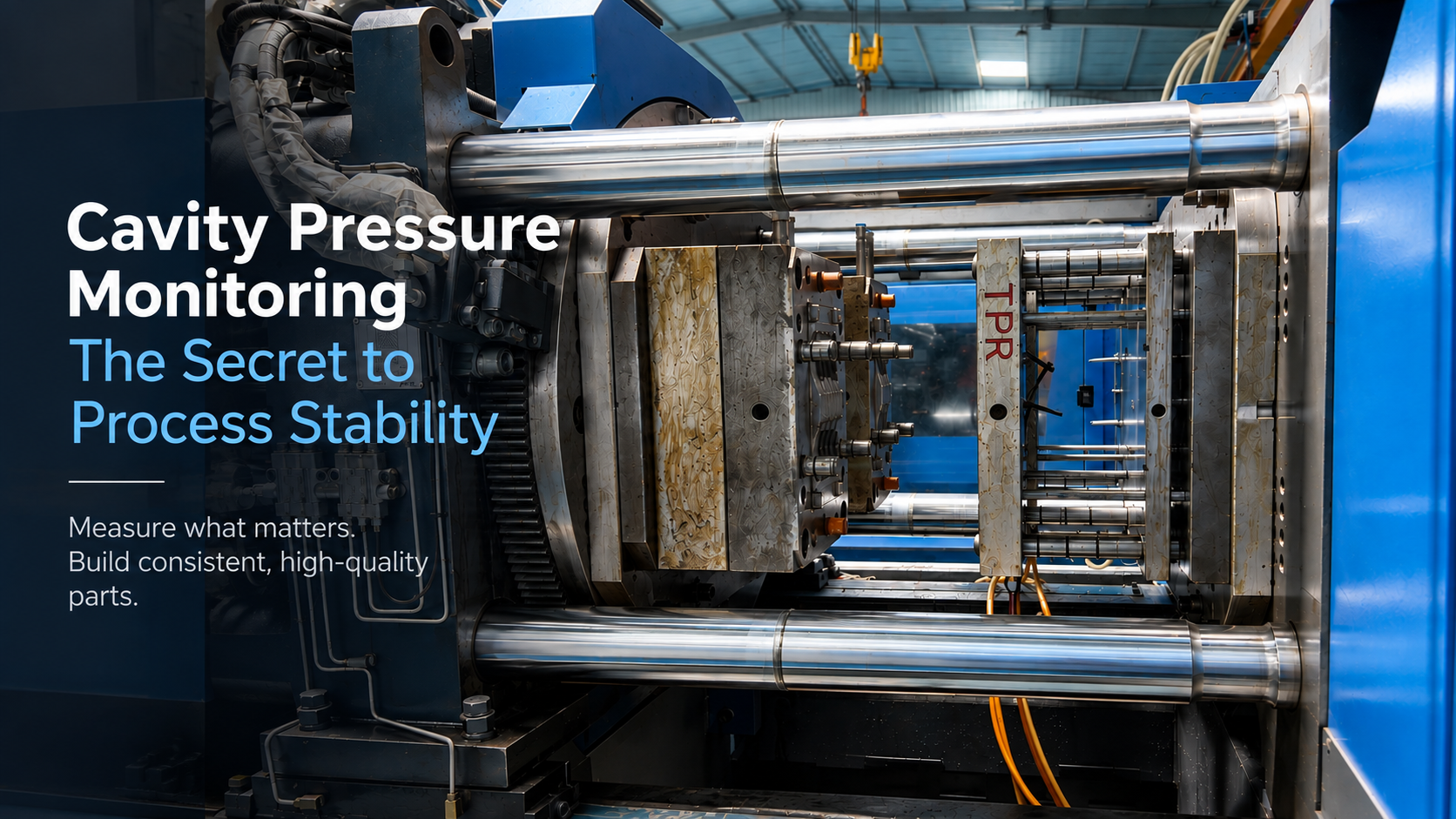
Once a job is running, inspection does not stop. Operators and quality technicians pull parts at defined intervals to check critical dimensions and cosmetic requirements while the job is live. Catching drift early, rather than at the end of a shift, keeps a small deviation from becoming a large batch of nonconforming parts. Where appropriate, at-press checks feed statistical process control so trends are visible before a limit is crossed.
Cosmetic defects deserve their own attention, because appearance requirements are easy to interpret differently from one inspector to the next. Common molded-part cosmetic issues include sink marks, flash, splay, weld lines, and short shots. Agreeing on written acceptance criteria and, where useful, physical boundary samples that show the limit between acceptable and unacceptable removes guesswork and keeps judgments consistent across shifts and operators.
Dimensional Inspection Tools
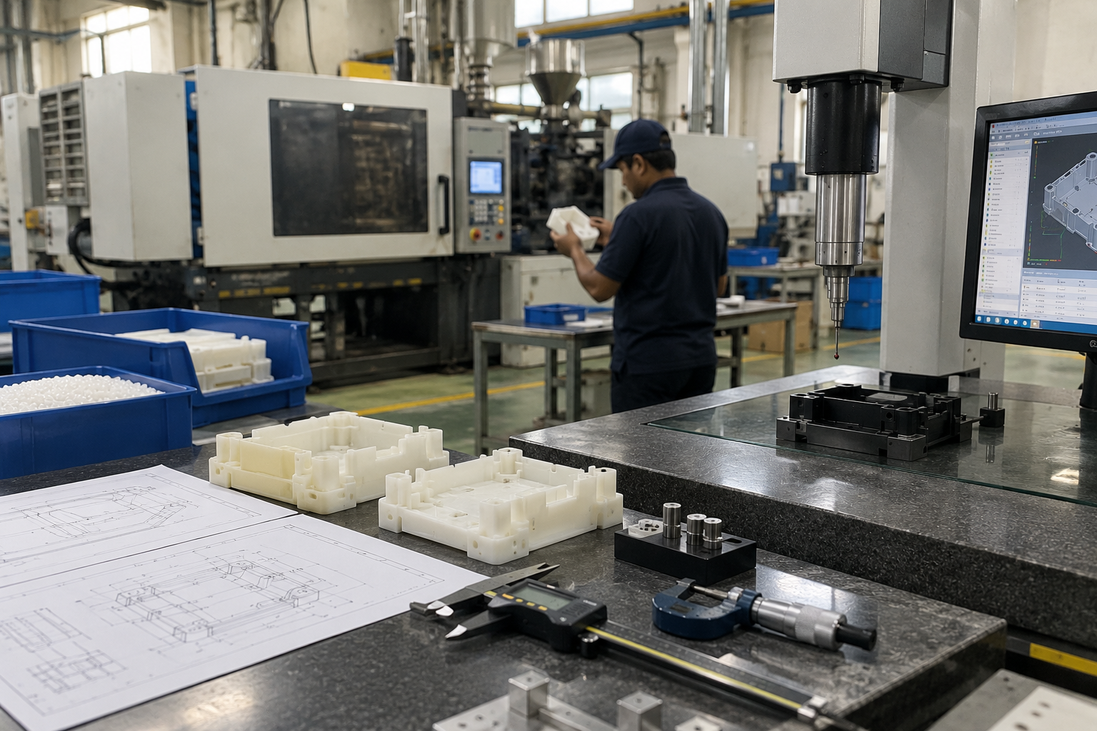
Different features call for different tools, and part of good QC is choosing the right one for the job.
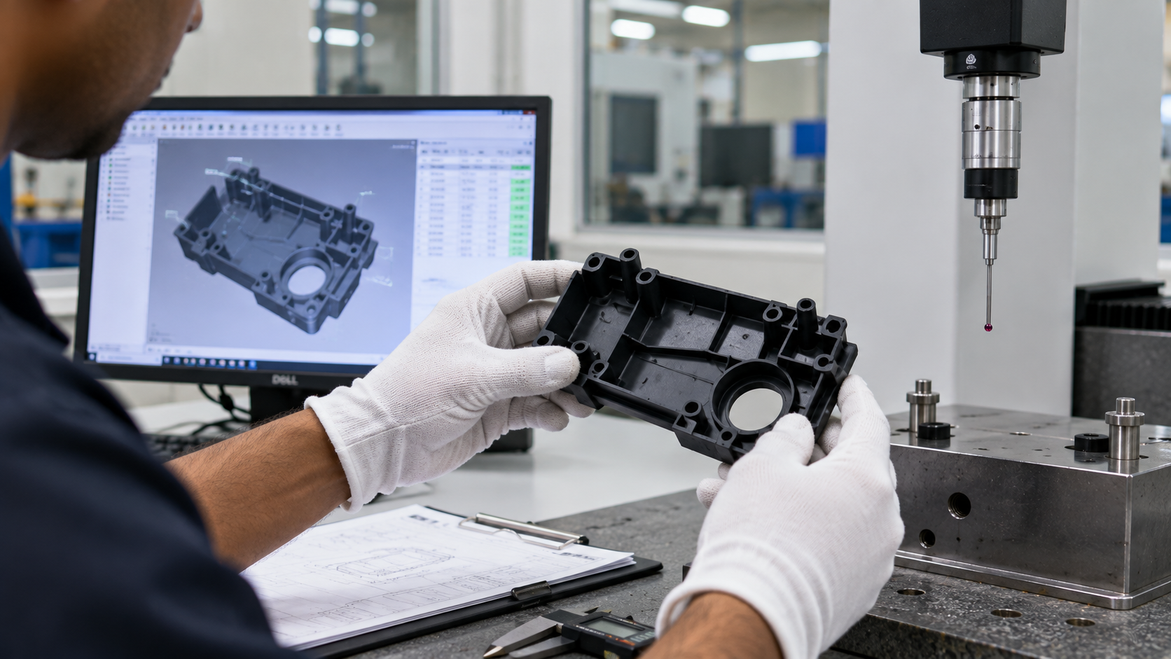
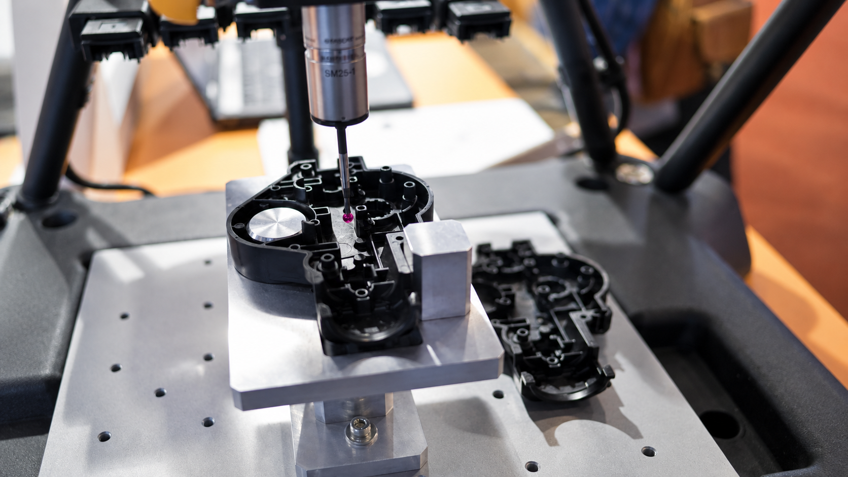
- Coordinate measuring machines (CMM) capture precise three-dimensional coordinates and are well suited to tight-tolerance features and complex geometry. National metrology bodies such as NIST maintain the reference standards that make coordinate measurement traceable.
- Optical and vision systems measure many features quickly and are ideal for small, delicate, or high-volume parts where contact could distort a feature.
- Hand tools such as calipers, micrometers, and pin or plug gauges provide fast checks at the press and on the floor.
- Profilometers and surface tools verify texture and finish where cosmetics or sealing surfaces are specified.
All of these rely on a shared language for how tolerances are defined on the drawing. That language is geometric dimensioning and tolerancing, standardized in ASME Y14.5. When a print calls out position, flatness, or profile, GD&T tells everyone exactly how to interpret and measure it.
Trusting the Data: MSA and SPC
A measurement is only useful if the measuring system is reliable, so before trusting the numbers we evaluate the measurement system itself. Measurement systems analysis (MSA), including a Gage R&R study, quantifies how much of the observed variation comes from the gauge and the operators rather than the parts. A common guideline treats a study result under 10 percent as acceptable, 10 to 30 percent as marginal depending on the application, and above 30 percent as unacceptable. If the gauge cannot tell good parts from bad reliably, no amount of measuring will help.
With a trustworthy measurement system in place, statistical process control (SPC) tracks the process over time. Control charts, described in the ISO 7870 series, distinguish normal variation from a real shift that needs attention. Capability indices summarize the picture: Cp compares the process spread to the tolerance, while Cpk also accounts for how well the process is centered. As a rough reference, a Cpk of 1.33 is often treated as capable and 1.67 as a higher bar, though the required value depends entirely on the customer and the characteristic.
Traceability and Nonconformance
Every measurement instrument on a critical feature should be calibrated on a schedule and traceable to a recognized standard. When a part does not conform, a documented process isolates the affected material, determines the cause, and defines corrective action so the same issue does not recur. Records tie parts back to material lots, process data, and inspection results, which is what makes a quality claim verifiable rather than a promise. You can see how this connects to our broader capabilities on our [Internal Link: Quality Assurance] page.
Frequently Asked Questions
How do you inspect injection molded parts?
Through layered checks: incoming material verification, first article inspection, in-process checks at the press, and final dimensional inspection using tools such as CMMs, vision systems, and gauges, all backed by SPC and calibration records.
What is a CMM and why use one?
A coordinate measuring machine captures precise 3D coordinates of part features. It is used for tight-tolerance dimensions and complex geometry where hand tools lack the accuracy or repeatability required.
What is Gage R&R?
Gage R&R is a study within measurement systems analysis that estimates how much measurement variation comes from the gauge and the operators. It confirms the measuring system is reliable before its data is used to judge parts.
What is the difference between FAI and in-process inspection?
FAI is a one-time, comprehensive verification that the process can produce a conforming part before full production. In-process inspection is ongoing sampling during the run to confirm the process stays within limits.
What Cpk do you hold?
The target Cpk depends on the customer requirement and the specific characteristic. Common references are 1.33 and 1.67, but the value should be agreed on for each critical dimension rather than assumed.