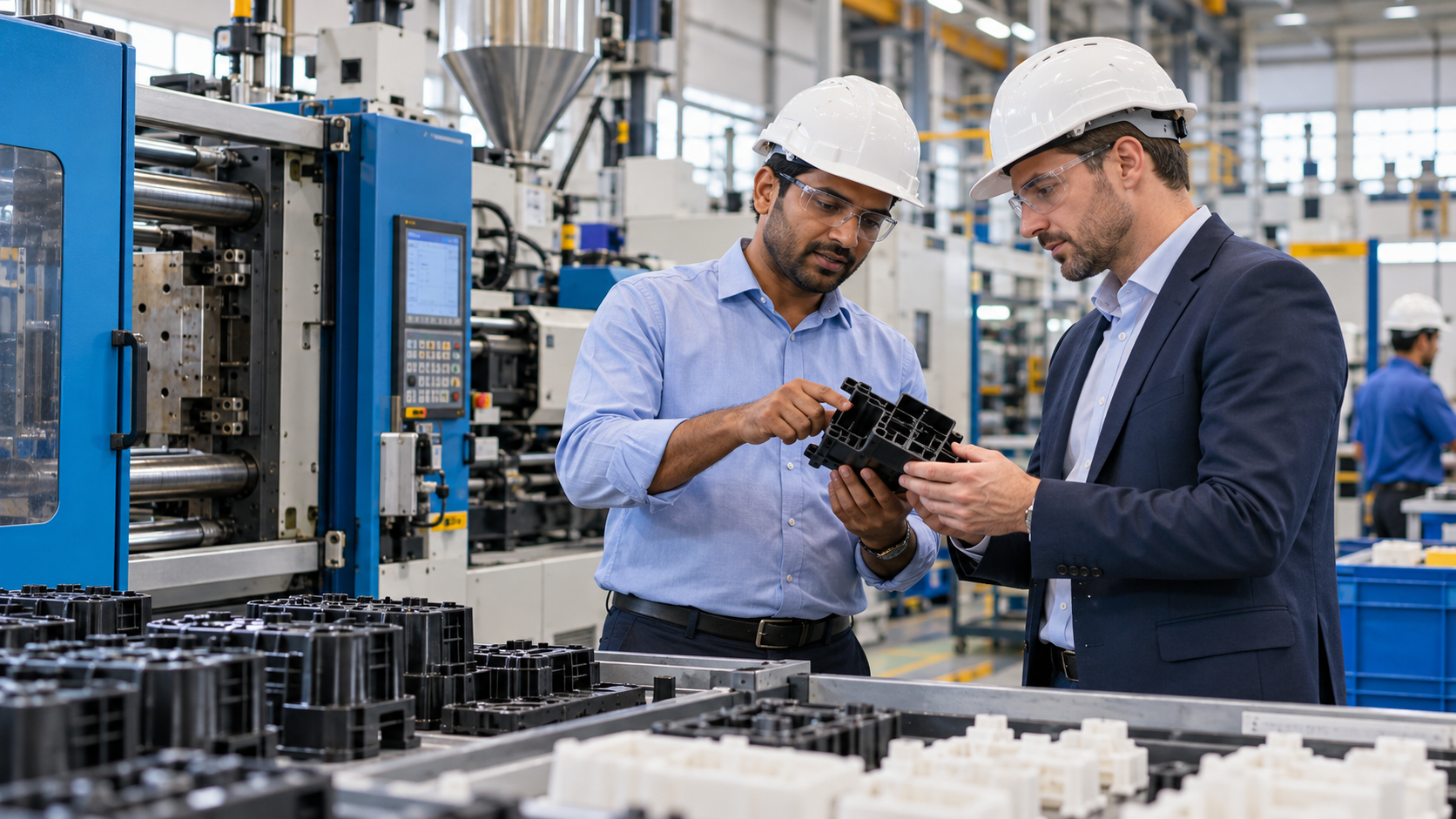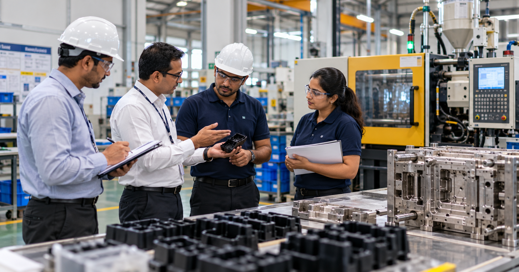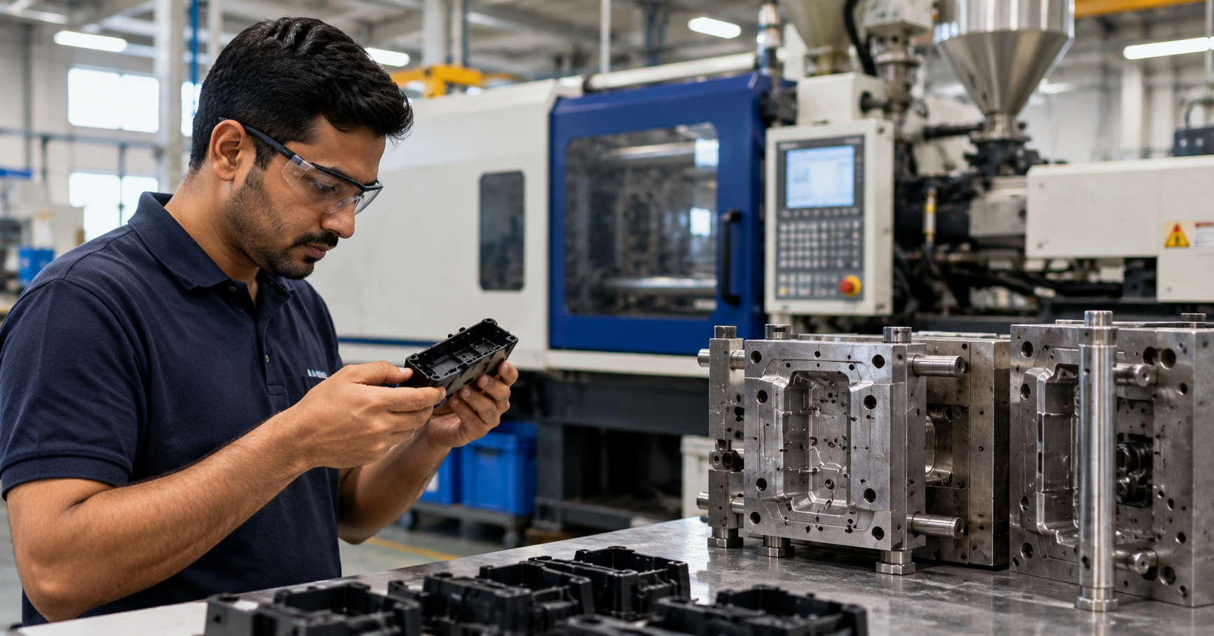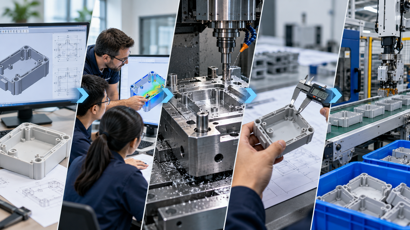
Every product team eventually asks the same question: how long will it actually take to go from the prototype we have in hand to parts coming off a production line? The answer most molders give, if they are honest, is 8 to 16 weeks from finalized design to first production run, with some programs stretching further for complex multi-cavity tools or heavily regulated applications. This range is consistent with timelines published by established molders such as Wundermold and sourcing platforms like Fictiv.
That range hides a lot of variation. The difference between a program that lands on 8 weeks and one that stretches to 20 is almost never luck. It is usually DFM discipline, tooling strategy, and the quality of communication between the product team and the molder.
This article walks through the typical path from prototype to production, stage by stage, with realistic timeframes and the specific decisions that make each stage faster or slower.
Stage 0: Prototype validation (before the clock starts)
Before you commit to a production tool, you should know your part works. Prototyping is usually done through one or more of:
- 3D printing in SLA, SLS, or MJF for form and basic fit
- CNC machining in the actual production resin for functional testing
- Low-volume rapid tooling in aluminum for parts that need to behave like molded ones
If you move into production tooling with a prototype that has not been functionally validated, every design change you discover later costs you tool rework, which is where timelines quietly double. Prototype validation is not part of the 8 to 16 week clock, and it is the stage buyers most often shortchange.
Stage 1: DFM review and quoting (1 to 3 weeks)
With a validated design, the first real step is a Design for Manufacturability review. A good molder will look at your CAD and raise questions about:
- Wall thickness variation and shrink behaviour
- Draft angles on vertical faces
- Gate location and gate type
- Rib and boss geometry to avoid sink marks
- Undercuts, side actions, and lifters
- Ejection strategy and witness marks
- Surface finish and cosmetic requirements
- Material selection, including flow length and fill pattern
Expect to iterate on the DFM once or twice. For straightforward parts, this stage is a week. For complex geometry with cosmetic surfaces, it can take three. A molder who refuses to do a serious DFM before you place the tooling PO is a molder who will bill you for every change later.
In parallel, the molder will issue a formal quote covering tooling, part price at projected volumes, lead time, and payment terms. Reputable molders will often provide this quote and basic DFM feedback at no cost, as noted by platforms like Fictiv.
Stage 2: Mold design and approval (1 to 2 weeks)
Once the tooling PO is placed, the mold designer will produce a detailed mold layout. You should expect to see and approve:
- Overall mold base and plate layout
- Cavity and core design
- Cooling channel layout
- Runner and gate system
- Ejector plate and ejection scheme
- Side actions, lifters, and any complex mechanisms
- Steel selection and expected hardness
Review this seriously. A sign-off here is a sign-off on how the tool will behave for its entire life. Mold flow analysis using tools like Moldflow or Moldex3D is often done at this stage for critical parts to simulate fill, pack, cooling, and warpage before cutting steel.
Stage 3: Tooling (4 to 10 weeks)
This is the longest single stage, and the one with the most variation. Rough rules of thumb:
- Aluminum prototype tooling for low-volume runs can be completed in 2 to 4 weeks
- Standard single-cavity production tool in P20 or similar steel typically takes 5 to 7 weeks
- Hardened multi-cavity production tool in H13 or S136 takes 8 to 12 weeks or more
- Complex multi-component tools with hot runners, side actions, and multiple lifters stretch to 12 to 16 weeks
During this stage, a disciplined molder will share weekly progress updates with photographs of the mold at each milestone: base, cavity blocks, core detail, ejection, cooling drilled, polishing, assembly. If your supplier goes dark for weeks at a time during tooling, something is wrong.
Stage 4: T1 sampling (1 to 2 weeks)
T1 refers to the first mold trial. The tool is mounted in the press for the first time, a process is set, and the first shots are taken.
What you get out of T1:
- First-shot parts for dimensional inspection
- Initial process parameters: injection speed, pack pressure, cooling time, cycle time
- A dimensional report comparing measured values to the CAD and drawing tolerances
- Observations on fill, flash, sink, warpage, and any ejection issues
- A list of mold corrections before T2
T1 almost always surfaces something. Expect at least one round of mold corrections. For well-designed parts and well-reviewed DFM, T1 is close to acceptable and corrections are minor.
Stage 5: T2 and process validation (1 to 3 weeks)
After mold corrections, T2 confirms that the tool is now capable. For many programs, T2 parts are what the buyer actually signs off on.
Depending on the regulatory environment, this stage may also include:
- PPAP (Production Part Approval Process) for automotive and industrial programs, typically at Level 3 for new tools, following AIAG guidelines
- IQ, OQ, and PQ validation for medical and pharma under ISO 13485
- First Article Inspection (FAI) reports per AS9102 for aerospace
- Scientific molding studies such as viscosity curves, cavity balance, pressure drop, and gate seal studies to define the production process window
This stage is where process capability is established. A good molder will not just hand over acceptable parts; they will hand over a documented, repeatable process.
Stage 6: Pilot run and ramp (1 to 2 weeks)
Before full production, most programs include a pilot run of a few hundred to a few thousand parts to verify:
- Cycle time at steady state
- Scrap rate under normal conditions
- Secondary operations such as pad printing, ultrasonic welding, or assembly
- Packaging and labelling to buyer specification
- Logistics flow from the press through QC to dispatch
Pilot results feed the ramp plan for full production. Where volumes are large, molders will typically ramp in phases, running a small percentage of planned volume for the first week, scaling to full volume over two to four weeks.
Stage 7: Full production
Full production is the easy part if the earlier stages were done right. The molder runs the agreed process on the agreed press, inspects at agreed intervals, and ships to the agreed schedule.
What a buyer should monitor during full production:
- On-time delivery against the schedule
- Rejection and PPM trends
- Customer complaints and their corrective actions
- Mold maintenance interventions and their frequency
- Any process drift signaled by cycle time, scrap, or dimensional data
Programs run smoothly when both sides agree on a scorecard and review it monthly.
Putting it together: a realistic 12-week timeline
For a representative mid-complexity program with a single-cavity P20 tool, a realistic calendar looks like:
- Week 1 to 2: DFM review, quote, and tooling PO
- Week 3: Mold design and approval
- Week 4 to 9: Tooling
- Week 10: T1 sampling and corrections
- Week 11: T2 and process validation
- Week 12: Pilot run and ramp into production
Simpler parts in aluminum tooling can compress this to 8 weeks. Complex multi-cavity programs with regulatory validation can stretch to 20 weeks or more. A molder who promises production in 4 weeks on a steel multi-cavity tool is either skipping steps or will slip.
What quietly extends timelines, and how to avoid it
The common timeline killers, in no particular order:
- Design changes after tooling has started
- Unresolved cosmetic requirements that only surface at T1
- Material changes forced by supply issues after the mold has been designed around a specific resin
- Unclear acceptance criteria that lead to prolonged T1 and T2 iteration
- Approval delays on the buyer side, especially during holidays
- Secondary processes added late, such as metal inserts or additional post-processing
Most of these are avoidable. A disciplined DFM, a clear drawing with real tolerances, a signed-off acceptance criteria sheet, and a buyer-side approval SLA will save you more time than any amount of expediting at T2.
How FD Group plans programs
Our standard program plan uses this timeline as the baseline, with named milestones, weekly checkpoints, and a shared tracker that both sides update. If you are planning a launch and want a realistic timeline for your specific part and volume, share your CAD and target volume and we will come back with a dated milestone plan rather than a vague estimate.
Done well, the walk from prototype to production is predictable, boring, and on time. That is exactly what it should be.