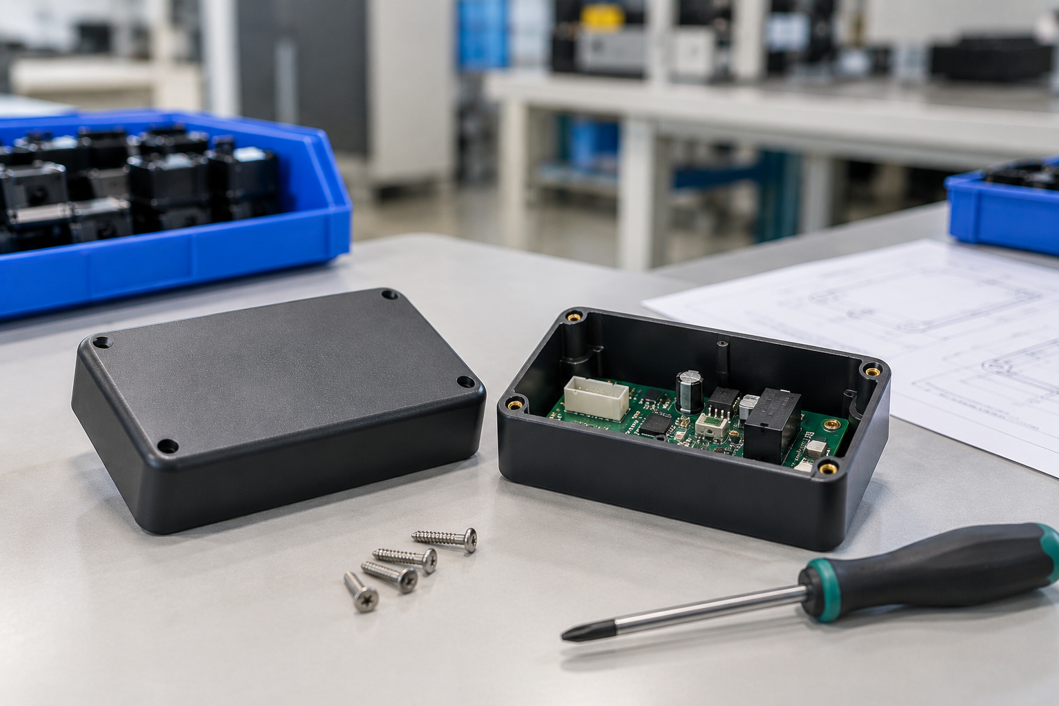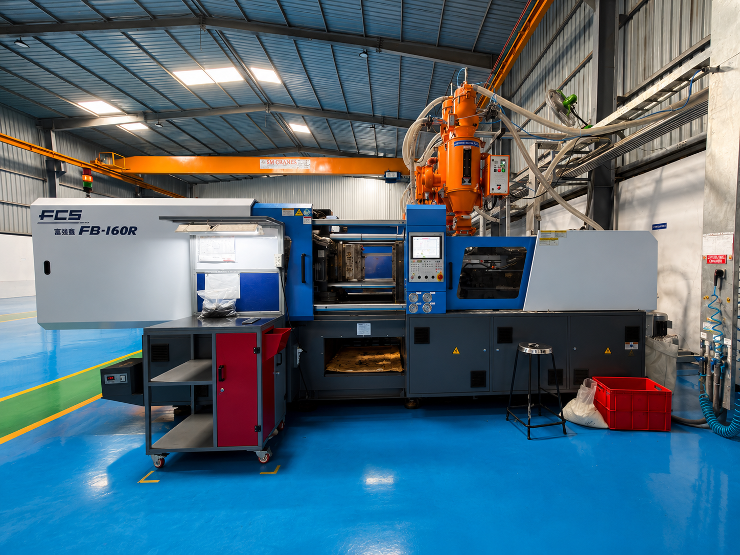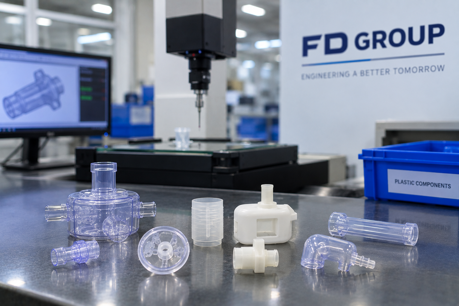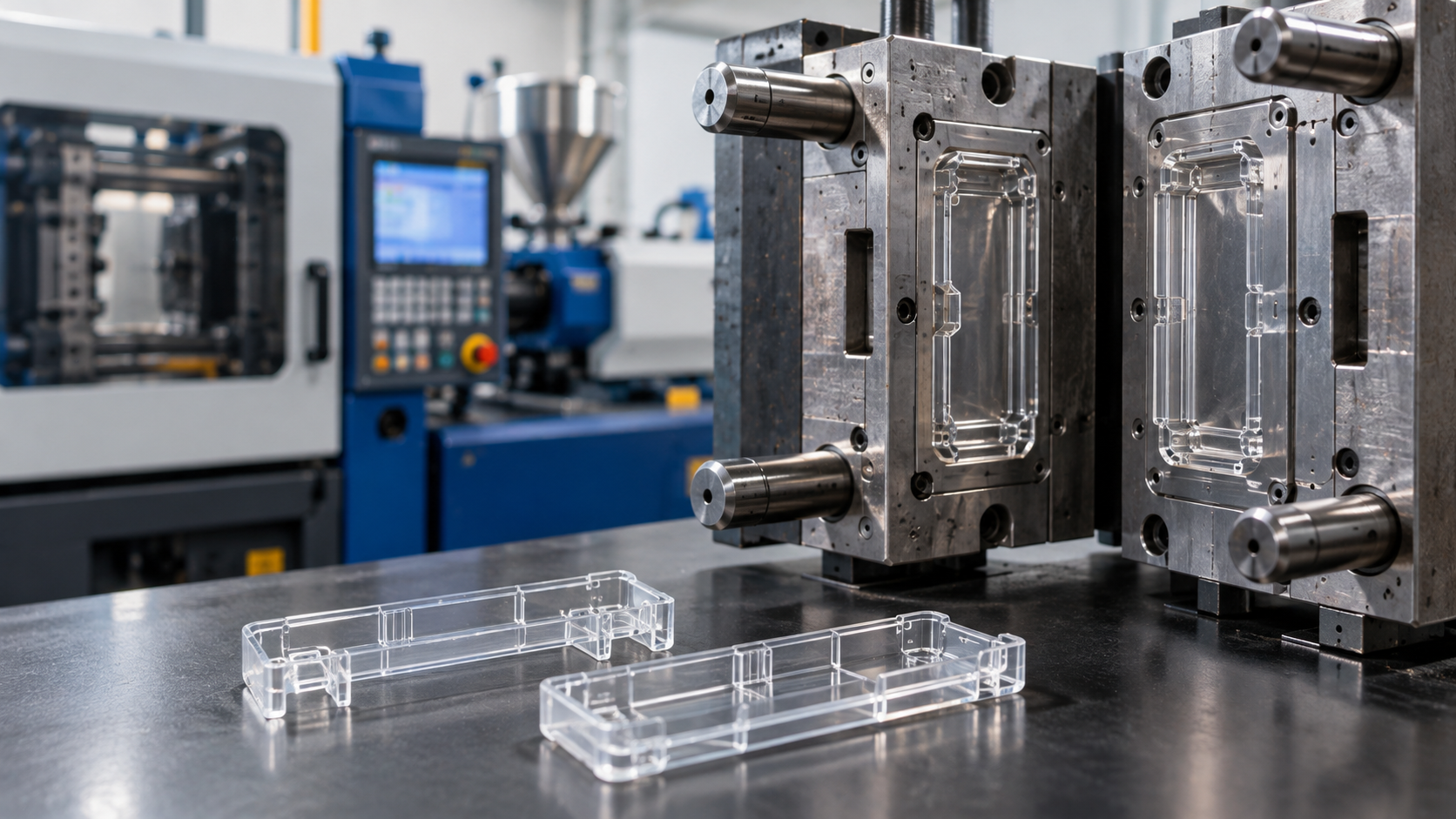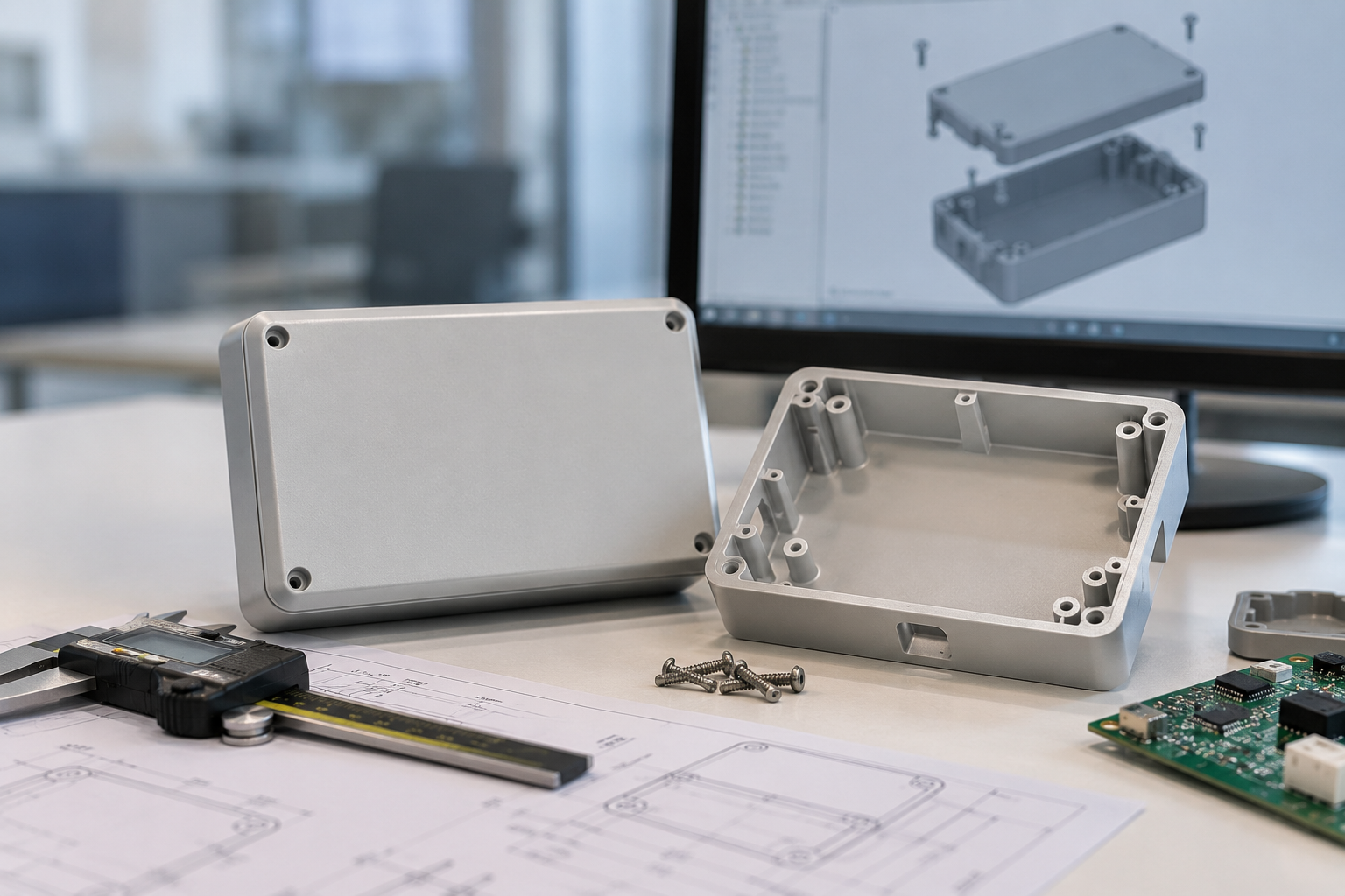
An electronics enclosure has an unusually demanding job for something people rarely think about. It has to look clean and feel solid in the hand, protect the electronics inside, allow assembly and service, sometimes manage heat or shield against interference, and do all of it at a cost that survives a competitive market. Most of the problems that show up late — visible sink marks, panels that bow, snaps that fatigue, seams that don't line up — trace back to design choices made before anyone thought about the mold.
Getting an enclosure right for injection molding is less about any single rule and more about designing with the molding process in mind from the start. The sections below cover the features that most often decide whether a housing molds cleanly or fights the tool.
Wall thickness sets the tone
Wall thickness is the foundation every other decision sits on. The aim is a wall that is uniform and appropriate for the material, because uneven walls cause the classic defects: thick sections cool slowly and sink, thin sections may not fill, and the difference between them drives warpage as the part shrinks unevenly. When a design needs a thicker region for stiffness, it is usually better to add a rib than to thicken the wall.
There is no single correct number — it depends on material, part size, and flow length. What matters is consistency and designing transitions gradually rather than abruptly.
Draft angles make ejection clean
Every face parallel to the direction the mold opens needs draft — a slight taper that lets the part release without dragging. Too little draft marks cosmetic surfaces, strains ejection, and shortens tool life. Textured surfaces need more draft than smooth ones because the texture itself resists release. Draft is easy to add early and awkward to retrofit once the geometry is locked.
Ribs and bosses, done properly
Ribs add stiffness without adding wall thickness, but they follow proportions. A rib that is too thick where it meets the wall pulls a sink mark on the opposite cosmetic surface; a common guideline keeps rib base thickness to roughly half to two-thirds of the adjoining wall. Ribs also need their own draft and generous root radii to keep material flowing and stress low.
Bosses — the towers that receive screws or locate parts — behave like thick sections when solid, so they are usually cored and supported with gussets rather than left as a solid mass. Screw towers deserve particular attention: the boss inner diameter, wall around it, and any ribs tying it to the wall all affect both strength and whether it sinks or voids.
Snap fits versus screw towers
Snap fits reduce fasteners, speed assembly, and cut cost, but they concentrate stress at the hook and hinge. The material's flexibility and fatigue behavior decide whether a snap survives repeated opening or cracks on the third service. Screw bosses give a more serviceable, repeatable joint at the cost of fasteners and assembly time. Many enclosures use both — snaps for the main closure, screws where the joint must be reworked or hold load.
Parting lines, gates, and where defects hide
The parting line — where the two mold halves meet — leaves a witness line on the part, so its position is a cosmetic decision, not just a tooling one. Gate location determines how the cavity fills, where weld lines form when flow fronts meet, and where cosmetic blemishes or warpage appear. On a visible housing, the goal is to push weld lines and gate marks into hidden or non-critical areas. These choices are far cheaper to influence at the design and DFM stage than to correct in steel.
Sink, warpage, and cosmetics
Sink marks and warpage are usually symptoms of the same root causes: uneven wall thickness, thick features behind cosmetic surfaces, and imbalanced cooling. Designing uniform walls, coring out mass, and proportioning ribs and bosses correctly removes most of the risk before processing has to compensate for it.
Cosmetic requirements then layer on top. Surface finish — from high gloss to fine texture — interacts with material, draft, and gate position. Gloss surfaces reveal every flow line and sink; texture hides minor imperfections but demands more draft. Deciding the cosmetic standard early lets the tool and process be built to hit it.
EMI and shielding, where relevant
Some enclosures need to manage electromagnetic interference. Plastic housings can be paired with conductive coatings, shields, or shielding gaskets, and mounting features for those elements are easier to integrate into the molded part than to add later. If shielding is a requirement, it belongs in the enclosure design from the outset.
From prototype to production
Prototypes validate fit, feel, and function, but a design optimized only for a prototyping method can carry features that are awkward or costly to mold at volume. Planning the transition — reviewing the design for manufacturability before tooling — keeps the production version faithful to the validated one without surprises. This is where an experienced molding partner earns its place: catching the issues on paper, where a change costs a fraction of what the same fix costs once the tool is cut.
FD Group perspective
FD Group approaches enclosure work from manufacturability first, reviewing geometry for wall uniformity, draft, rib and boss proportions, and gate strategy before steel is cut, and running mold flow analysis where it helps. With in-house tooling and controlled assembly and inspection, the path from a validated design to consistent, cosmetically clean production parts stays under one roof.
Bringing a new device to life? Send FD Group your enclosure design for a manufacturability review before tooling — start a technical conversation at www.fdgroup.co.in.