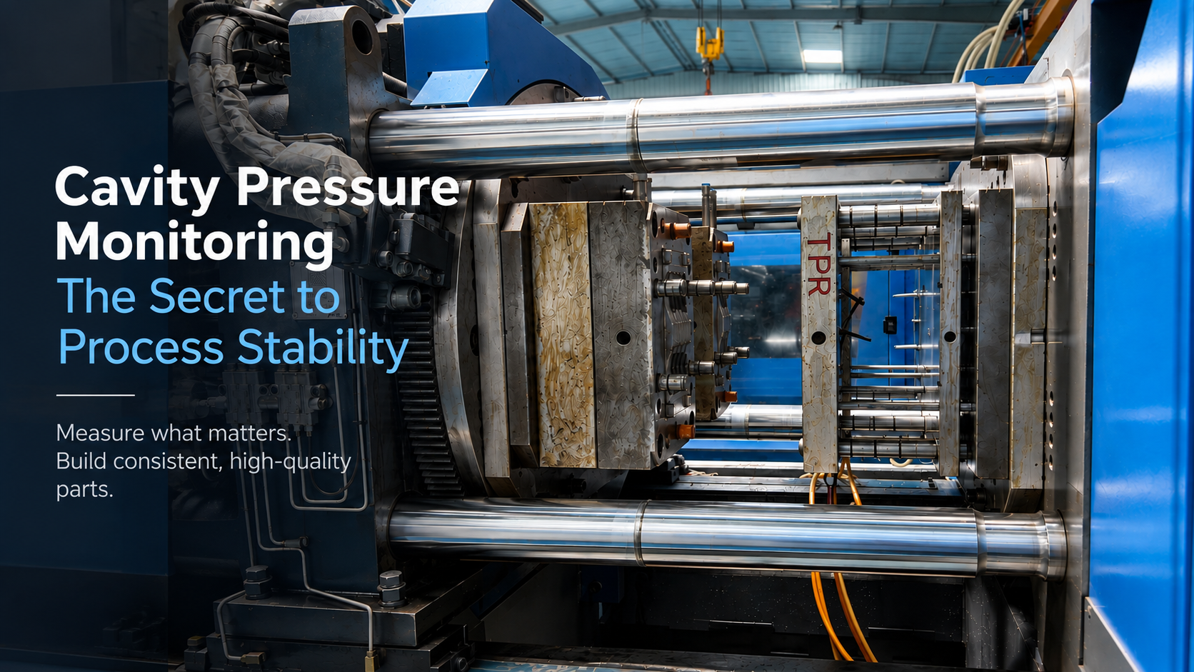
An injection molding machine reports a lot of numbers, including injection pressure, screw position, and cycle time. None of them tell you directly what the plastic is doing at the one place that decides part quality, which is inside the cavity. Between the screw and the cavity, pressure is lost through the nozzle, sprue, runner, and gate, and viscosity shifts with every change in material and temperature. Cavity pressure monitoring closes that gap by measuring pressure where the part is actually formed. For molders chasing consistent, repeatable production, it is one of the most powerful tools available. This article explains how it works and why it stabilizes a process.
Why Machine Settings Do Not Tell the Whole Story
Imagine two consecutive shots with identical machine settings. On one shot, the check ring seals a fraction of a second later, or the melt is slightly cooler, or a small amount of material degrades. The machine may report nearly the same pressure at the screw, yet the pressure the plastic sees inside the cavity can be noticeably different. Because cavity pressure reflects the combined effect of everything upstream, it is a far more direct indicator of what the finished part will look like than any single machine setting. Resources from RJG describe in detail why in-mold data outperforms machine data for this reason.
How Cavity Pressure Sensors Work
Cavity pressure is measured with sensors, most commonly piezoelectric, installed in the mold. There are three general approaches, each with trade-offs.
- Direct sensors sit flush with the cavity wall and contact the melt. They give the most accurate reading but leave a small witness mark, so they are placed where cosmetics allow. Manufacturers such as Kistler offer sensors designed for these positions.
- Indirect sensors sit behind an ejector pin and read the force transmitted through the pin. They do not mark the cavity surface and are a practical choice for multi-cavity tooling.
- Contact-free sensors measure strain in the mold wall itself, which suits cosmetic, optical, or very low-viscosity applications where nothing should touch the melt.
The right choice depends on the part, the surface requirements, and how many cavities need to be monitored.
Reading the Cavity Pressure Curve
The real value comes from the pressure curve over a single cycle, which tells a story. Pressure rises as the cavity fills, peaks during packing, then decays as the part cools and the gate freezes. Several features of that curve matter:
- The transfer point where filling switches to packing can be triggered on cavity pressure rather than screw position, which keeps the switchover consistent even as viscosity drifts.
- Peak cavity pressure correlates strongly with how well the part is packed and often with critical dimensions.
- The area under the curve, or pressure integral, summarizes the total packing energy the part received.
- Gate seal appears as the point where cavity pressure stops responding to hold pressure, confirming the correct hold time.
Independent, peer-reviewed research on in-mold sensors has documented how these signals relate to part quality and process control.
From Monitoring to Control
Monitoring alone is useful, but the bigger gains come when cavity pressure drives the process. Using pressure to set the fill-to-pack transfer makes that critical moment repeatable. In an advanced decoupled setup, the process can pack to a target cavity pressure rather than a fixed screw position, so the plastic receives the same treatment every shot regardless of small upstream changes. This ties directly into the broader method described in our [Internal Link: Scientific Molding] article.
Cavity pressure also enables automated quality decisions. If a shot's pressure signature falls outside validated limits, the system can flag or divert that part before it reaches the customer. Instead of relying on end-of-line inspection to catch a suspect part, the molder contains it at the moment it is made.
Consider a common scenario: a regrind blend or a new material lot subtly changes melt viscosity. On a process controlled only by machine settings, the part might pack slightly differently and drift toward a sink mark or a dimension near its limit, and the problem might not surface until final inspection or, worse, at the customer. On a cavity-pressure-controlled process, the peak pressure and curve shape shift immediately and visibly, the affected shots can be contained automatically, and the process can be corrected before scrap accumulates. The sensor turns a hidden change into an obvious, actionable signal.
What It Means for Your Parts
For a buyer, the benefit is straightforward: shot-to-shot consistency, fewer defects escaping the cell, and a process that resists the drift that causes intermittent problems. On tight-tolerance or high-reliability parts, cavity pressure monitoring can be the difference between a process that merely passes on a good day and one that stays capable across shifts and lots. To see how it fits into a full program, review our [Internal Link: Manufacturing Capabilities] page.
Frequently Asked Questions
How do cavity pressure sensors work?
They measure pressure inside the mold cavity, usually with piezoelectric sensors, either directly at the cavity wall, indirectly behind an ejector pin, or through mold-wall strain, and report the pressure the plastic experiences as the part forms.
What is the difference between direct and indirect sensors?
Direct sensors contact the melt for the most accurate reading but can leave a small mark. Indirect sensors sit behind an ejector pin and read force through the pin, avoiding marks and suiting multi-cavity tools.
Can cavity pressure monitoring sort bad parts automatically?
Yes. When a shot's pressure signature falls outside validated limits, the system can flag or divert that part, containing a suspect part before it ships rather than relying only on final inspection.
Does cavity pressure monitoring improve capability?
By stabilizing the fill-to-pack transfer and confirming consistent packing and gate seal, it typically reduces variation, which can support better process capability. Results depend on the part, tool, and material.
Do the sensors mark the part?
Direct sensors can leave a small witness mark, so they are placed where cosmetics permit. Indirect and contact-free sensors avoid marking the visible surface.